
Analytical Biochemistry · Instrumentation
The Analytical Guide to MALDI-TOF Mass Spectrometry Troubleshooting Mass Accuracy
In high-throughput analytical biochemistry, achieving absolute precision during intact mass analysis is vital for verifying macromolecular structures. This guide maps every failure mode — from co-crystallisation defects to ion source contamination — and provides a structured engineering pipeline to restore sub-parts-per-million accuracy.

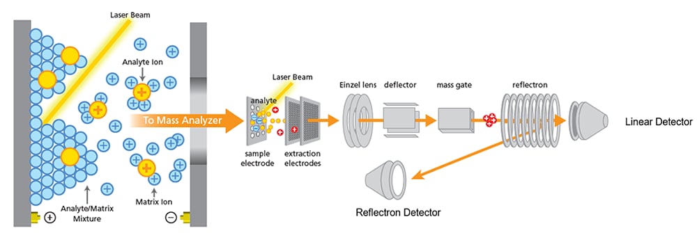
Researchers rely heavily on matrix-assisted laser desorption/ionisation time-of-flight instruments to process complex peptide and protein arrays. However, minor technical variations frequently introduce subtle mass shifts, poor resolution, or irregular signal baselines. Mastering MALDI-TOF mass spectrometry troubleshooting and mass accuracy is the only reliable way to prevent expensive re-runs and safeguard the integrity of quantitative datasets.
When your mass spectrum displays significant mass drift or peak assignment errors, you must systematically isolate hardware drift from sample preparation issues. Treating this diagnostic process as a structured engineering pipeline allows you to restore sub-parts-per-million accuracy quickly. By following a diagnostic tree from the initial sample preparation check down to the final resolution evaluation loop, you can pinpoint the exact cause of any mass-shifting artefact.
The Chemistry and Hardware Diagnostic Matrix
To keep your time-of-flight analyser performing at peak resolution, you must align your sample matrix choice with specific target molecular weights while maintaining strict control over laser energy delivery. The table below maps each checkpoint to its root cause and the optimal corrective action.

| Diagnostic Checkpoint | Common System Flaw | Root Physical Cause | High-Value Optimisation |
|---|---|---|---|
| Matrix Selection | High chemical noise below 1,500 Da | Incorrect matrix type (e.g. sinapinic acid for small peptides) | Use α-cyano-4-hydroxycinnamic acid for low-MW targets |
| Co-Crystallisation Check | Erratic spot-to-spot intensity; extreme baseline fluctuations | Slow solvent evaporation causing inhomogeneous target ring formations | Optimise matrix-to-analyte ratio; execute rapid thin-layer deposition |
| Calibration Review | Systemic mass shifts across the full acquisition window | Thermal expansion of the flight tube or aged external calibration standards | Run a fresh multi-point internal calibration adjacent to sample spots |
| Laser Pulse Tuning | Severe peak broadening and detector saturation artefacts | Excessively high laser intensity destroying sample molecules during ablation | Step down laser pulse power to find the true threshold energy minimum |
| Ion Source Evaluation | Gradual resolution drop below 5,000 in the mid-mass range | Contaminants and matrix buildup coating acceleration grids and extraction plates | Execute a dedicated ion source cleaning protocol to restore uniform electrical fields |

Restoring Mass Accuracy: A Sequential Workflow
When systematic errors cause target mass assignments to drift beyond acceptable parts-per-million boundaries, follow this four-phase operational sequence to locate and resolve each issue in order of increasing technical intervention.
Audit Target Co-Crystallisation Quality — Phase 1
Examine the target plate under a laboratory microscope. Ensure crystals are uniform and tightly packed, because large irregular crystal structures create height variations that warp flight-time calculations.
Execute Multi-Point Instrument Calibration — Phase 2
Prepare fresh external calibration standards that perfectly bracket your expected target mass range. Update calibration software parameters to compensate for any minor electronic or ambient temperature drift.
Optimise Laser Intensity and Delayed Extraction — Phase 3
Gradually increase laser power from zero until you reach the absolute threshold of signal generation. Simultaneously adjust delayed extraction time settings to ensure all generated ions enter the flight tube in a tight, uniform packet.
Perform Grid Voltage and Vacuum Maintenance — Phase 4
Verify that system vacuum remains firmly below the recommended microtorr limit. If mass accuracy continues to drift, verify acceleration grid voltage stability to ensure no local charging effects are altering ion paths.

Why does a poor matrix-to-analyte ratio cause significant baseline noise?
When analyte concentration is too high relative to the matrix compound, the sample cannot isolate effectively within the crystal lattice. Laser energy hitting the sample causes thermal degradation rather than smooth ionisation, producing a high volume of uninformative chemical fragments manifest as severe baseline noise across lower mass ranges.
How does delayed extraction optimisation directly improve mass resolution?
During the initial laser pulse blast, ions of the same mass are formed at slightly different depths and with varied initial kinetic energies. Instant acceleration voltage propagates these variances down the flight tube, causing broad peaks. A brief extraction delay allows faster ions to travel further before the field engages, giving slower ions a proportionally larger energy boost — focusing the entire packet perfectly at the detector.
What is the mechanical difference between external and internal calibration?
External calibration applies reference standards to separate spots, calculating a global correction factor. This handles broad hardware variations but cannot account for micro-variation on individual sample spots. Internal calibration mixes standards directly into the unknown sample matrix pocket, ensuring identical crystallisation and extraction conditions and yielding the highest possible mass accuracy.
When should you perform an absolute ion source cleaning protocol?
Over hundreds of high-power laser shots, matrix material vaporises and deposits onto extraction grids and acceleration plates, creating local insulating layers that build static charges during operation. These static fields deflect ion beam paths, causing progressive resolution drops and severe mass-shifting errors. If multi-point calibration routines fail to correct assignment drift, a physical source cleaning is necessary to restore electrostatic field uniformity.


0 Comments
We will get back to you as soon as possible and thanks for the comment.